The Process Diagram
This section introduces the Spatial Data Supply (SDS) business process which will be used for the first part of the exercise. This particular process belongs to an unspecified agency responsible for generation and dissemination of spatial data. The agency deliver data in either digital or analogue form. This business process can be used to request ,for example, cadastral data. A request for cadastral data is made using an object/parcel identifier. Cadastral objects in this case could be one of: parcel, ship, plane, city amenity or public lot. 1 shows the conceptual model of the SDS process, which was created using BPMN. We will use this model as a reference to generate a process definition in ProcessMaker. Make sure that you understand the example process and its different elements.
Description of the SDS process
Services are mainly requested by regular or registered clients (this counts for about 90% of the cases). A small number of request comes also from the general public (ad-hoc clients). Regular clients have on-line access to the services through the organisation’s web portal. These are professional clients such as municipalities, provincial and national governments, notaries, utility companies, financial institutions and real estate agents. Ad-hoc clients (non-regular) are basically members of the general public who occasionally need to make use of the organizations services. Specific characteristics of the SDS process include:
- Requests are made by clients via the web containing the following data:
- A geometry of the area where the cadastral objects of interest are located;
- the type of object, namely, parcel, ship, plane, city amenity, public lot;
- the type of delivery, namely, certificate or dataset;
- in the case of requests for datasets the client could choose for one of the following formats: Geography Markup Language (GML), Scalable Vector Graphics (SVG), Well-Known Text (WKT), Keyhole Markup Language (KML) or JavaScript Object Notation (GeoJSON);
- additionally clients provide a motivation for the request and a short title.
- New cases (requests) are assigned cyclically to the next service officer in line.
- Requests are reviewed by a service officer from the client service department, who determines if the requested data is available, and whether or not the selected object is a public area such a road, a park, etc. The service officer also provides some general comments for every request. If the data is not available the client will receive e-mail notification and the job is finished. Otherwise the job will continue to the data processing department. Currently the organisation can only manage requests for parcels, therefore request for other types of cadastral objects are temporarily rejected.
- All tasks within a case instance that are responsibility of the client service department are assigned to the same service officer who initially reviews the request. This includes service delivery and notification of unavailability of the requested data.
- Generation of datasets is the responsibility of data analysts. Data analyst use a self-service assignment method to claim cases. Generated datasets are attached to the process and later deliver to the client.
- Production of certificates is the responsibility of registrars. cases are assigned to registrars base on their nature. One employee deals certificates on public properties and a different employee deals with certificates on private properties.
- Creation of Invoices is the responsibility of financial assistants. Work here is assigned manually by the employee who generated a dataset or produced a certificate.
The steps of the SDS process have been capture in a process model which is depicted in 1. The model has been developed using BPMN as the representation language.
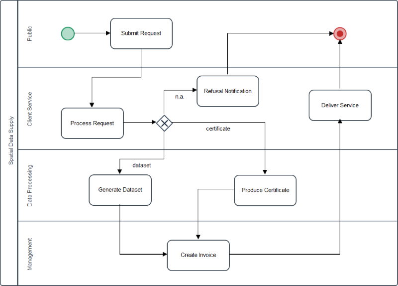
Description of the process swimlanes
| Swimlane | Description |
|---|---|
| Public | Initiates the process by making data request. |
| Client Service | Responsible for receiving requests and analysing availability. |
| Data Processing | Prepares data delivery according to specifications. |
| Management | Prepares Invoices. |
1 lists the descriptions of the swimlanes portrayed in 1. Each swimlane represents an organizational unit. An organisational unit corresponds to, for example, a department. 2 shows the users that participate in the process, including their identities, organizational units and business process roles. A business process role represents the type of activity that a user executes in a process.
Description of the process swimlanes
| Organizational Unit | Process Role | User (Identity) | Credentials (user/pass) |
|---|---|---|---|
| Client Service | Service Officer | Ding Feng Elin Bond June James Lisa Stark |
dingfeng/dingfeng elinbond/elinbond junejames/junejames lisastark/lisastark |
| Data Processing | Data Analyst | Rick Hanks Linda Clark |
rickhanks/rickhanks lindaclark/lindaclark |
| Registrar | Mike Foxx Holly Ross |
mikefoxx/mikefoxx hollyross/hollyross |
|
| Surveyor | Lacy Grey Theo Felix |
lacygrey/lacygrey theofelix/theofelix |
|
| Management | Financial Assistant | Mary Adams Sam Scott |
maryadams/maryadams samscott/samscott |
| Process Designer | Betty Davis Greg Moll Lucie Shaw |
bettydavis/bettydavis gregmoll/gregmoll lucieshaw/lucieshaw |
|
| Process Supervisor | Piet de Jong | pietdejong/pietdejong | |
| Public | Annie de A. Fozzy de F. Snuffy de S. Ernie de E. Grover de G. |
anniedea/anniedea fozzydef/fozzydef snuffydes/snuffydes erniedee/erniedee groverdeg/groverdeg |
|
Process Designer
To start working with ProcessMaker, open your browser (preferably Firefox) and navigate to the following URL:
Use workflow as the workspace name.http://owsgip.itc.utwente.nl:9090
This will bring up the ProcessMaker login screen, where you should enter the user credentials and select the desired workspace. There is one workspace configured for this exercise called: workflow. You should use this workspace to create your process diagrams and run process instances (this is valid for these exercises and any other process diagrams that you might need later on in the course).
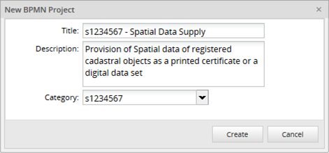
To start creating a process diagram we need to login as one of the users who is has the Process Designer role. Make sure your pick and login the right user and then use the corresponding user/password credentials (see 2). This will bring up the designer tab.
Click on the New button to create a new process diagram. Give it a distinctive name (e.g., s1234567 – Spatial Data Supply), and write a clear description of the process objective. Select your own student number, e.g., s123456 as the process category (see 2).
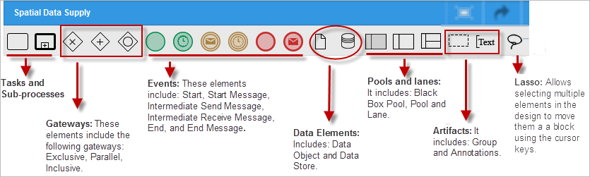
Now we have entered the designer area in ProcessMaker. This is the area where the representation of business processes is laid out in a visual manner using BPMN notation. The shapes toolbox, located at the top at the upper side of the designer includes the BPMN elements needed to create process diagrams (see 3)). You can drag any of this elements onto the canvas to add new items to your process.
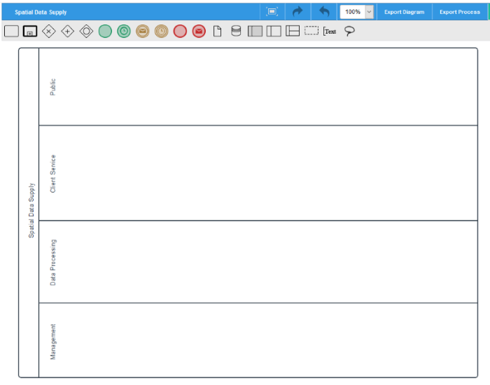
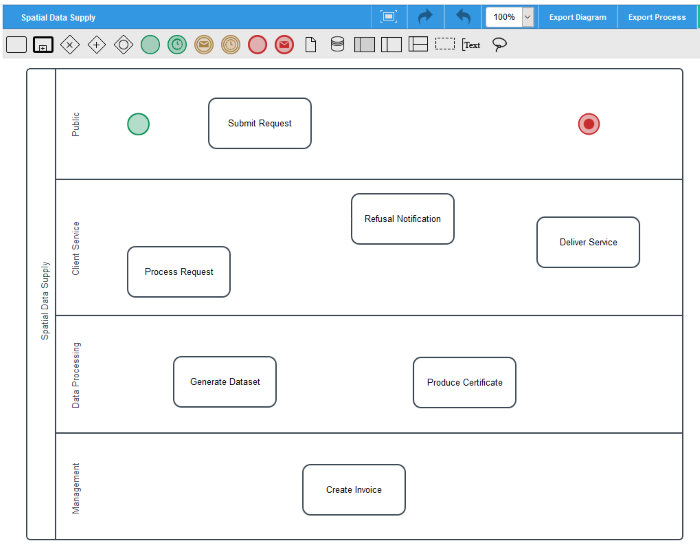
Remove any pre-existing elements and then drag a Pool and four Lanes into the canvas and give them their corresponding names, each lane corresponding to an organisational unit (see 4).
Insert seven tasks and place them in the corresponding lanes and given them appropriate names following the description of the SDS process. To rename a task or change other attributes of a task, simply right-click on the task and select Properties. ). Provide a description for every task so that when tasks are instantiated (see 5), users will get some details as to what is the task about.
Next, insert a Start and an End event. Events can be of diferent types. In the case of our End event we want to use it to completetly finalize the porcess, therefore we want to use the termination event type. To asign the evnt type, right click on the End event and then select 'End Event Type' followed by 'Terminate'. Your process diagram should for now look like 5.
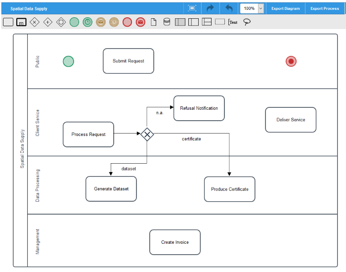
We are now ready to add a gateway to the process to evaluate the choices that take place after a request is processed. To do this we drag-n-drop an Exclusive Gateway on the canvas and connect it to the three potential task choices. This step will only create the connection flows, the actual conditions for each choice will be added later on.
Finally, double-click on the heads of the newly added connectors to add labels and descriptions to each choice (dataset, n.a., certificate). Your process diagram should now look like 6.
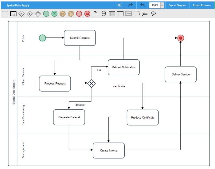
To complete the diagram, simply include the connection flows between the remainder tasks, which will result in a process diagram similar to that of 7.
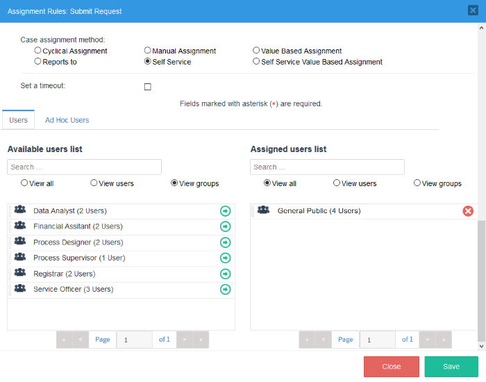
Although we have drawn the department lanes on the canvas, this does not automatically assign task to users on those departments. To assign users or groups to the various tasks requires two actions: first, specify the mechanism by which job instances will be allocated, second, assigning the group(s) or user(s) that are responsible for the execution of allocated instances.
To specify how users of a group are allocated to a job right-click on a task and select Assignment Rules. For each task select the appropriate Case assignment method. On the Available users list section, select the target group/user by clicking on the green arrow. Figure 1-8 shows this step for the Submit Request task. Repeat this step for all other tasks following the information in 3
Description of the process swimlanes
| Task | Assignment Rule | Group |
|---|---|---|
| Submit Request | Self Service | General Public |
| Process Request | Cyclical Assignment | Service Officer |
| Generate Dataset | Self Service | Data Analyst |
| Produce Certificate | Value Based Assignment | |
| Create Invoice | Manual Assignment | Financial Assistant |
| Refusal Notification | Value Based Assignment | |
| Deliver Service | Value Based Assignment |
We will revisit this step later on, to deal with the Value Based Assignment cases. For the time being we just leave the other parameters untouched. The various types of job assignments listed here are just as explained in the lectures.